UPDATE. Building Enclosure Modeling: BIM Techniques, Climate, and the Smaller Firm

MiamiBeachFlood - 1

Thank you to everyone who came to see my talk at Graphisoft BIM 2017 North America User Conference. As promised here are links to the files I used in my presentation (…and quite a few more). The best way to understand the details of talk is to dig into the PLA files and see how the bits are structured. I look forward to hearing your comments and keeping in touch.

PowerPoint

2017 GS NA User Conference Presentation HUGGINS.pptx (I have borrowed liberally from the Internet for cool images. Please let me know if I have misappropriated any of your intellectual property ands it will be promptly removed.)

Seewee Residence

1056 Seewee VEGAS.pla

1056 Seewee Technical.bimx

1056 Seewee Technical Core.bimx

1056 Seewee Main Floor.bimx

1056 Seewee Presentation.bimx

IOP Renovation

1051 IOP VEGAS.pla

1051 IOP Renovation Technical.bimx

1051 IOP Renovation 1-Entire Bldg.bimx

1051 IOP Renovation 2-Without Finishes.bimx

1051 IOP Renovation 3-Core Elements.bimx

1051 IOP Renovation 4-Core Load-Bearing Elements.bimx

Kiawah Renovation

1032 Kiawah VEGAS.pla (Ignore the missing object warning that appears in the Library Manager.)

1032 Kiawah Technical.bimx

1032 Kiawah Bunk Beds.bimx

—Enjoy!

Building Enclosure Modeling: BIM Techniques, Climate, and the Smaller Firm

MiamiBeachFlood - 1

Here’s a summary for a seminar I’ve submitted, which I hope to present at the Graphisoft BIM 2017 North America User Conference and the AIA 2017 National Convention. Please let me know your thoughts and follow my blog as the topic develops.

Abstract

By understanding the basic principles of effective building enclosures and applying BIM techniques smaller firms can improve analysis during design development and more clearly communicate enclosure requirements in their construction documents, thereby improving quality assurance and diminishing their professional risk.

Session Description

Building enclosure failures are common. Moisture problems are more likely to land you in court than structural issues. Mold is gold. What can you do? Understand the principles of effective enclosure design. Model it. Educate the team. This presentation will review the basic principles of building science in relation to thermal and moisture control. It will then explain how to use tools within ARCHICAD to model and illustrate thermal characteristics, drainage planes, air barriers, and vapor retarders within building enclosures. Specific ARCHICAD concepts include Building Materials, Priority Based Connections, Composites, Custom Profiles, Graphical Overrides, Selection Criteria, and Energy Evaluation.

Learning Outcomes

  1. Understand the basic principles of effective building enclosures in relation to thermal and moisture control.
  2. Establish priorities for the intersections of materials within the building enclosure.
  3. Identify and model the typical assemblies and intersections within the building enclosure.
  4. Demonstrate proper construction techniques in 3D using whole building models, assembly sequences, and cutaway details.

I’m Back!

KenPeopleMatter740x184

Building Enclosure Modeling

I’m back with a new mission: To marry my two biggest technical obsessions—BIM and building enclosure design. Call it building enclosure modeling, which has just begun to emerge as a topic for building science and the AEC industry.

Tempus Fugit

A lot has changed in ARCHICAD. We now capitalize the whole name. There have been 4 upgrades. Some great new functionality has been added—Priority Based Connections, Building Materials, Energy Evaluation Improvements, 3D Documents, Integrated CineRender Engine, Tab-Based Navigation, Graphical Favorites,  and Graphic Overrides. My old favorite the Element ID can now have 2,048 characters, quite an improvement from 15, meaning more descriptive, less cryptic naming. All good.

I’ve been busy, especially with the Building Enclosure Council. I spent two years as Vice Chair and then two more as Chair of the Charleston Chapter, which included a stint on National Building Enclosure Council Board and National Advisory Board Member for BETEC (Building Enclosure Technology & Environment Council a unit the National Institute for Building Sciences).

I’ve met a lot of smart people. I’ve been to numbers of national conferences. Lots of exciting things going on.

I got Jared Banks, whom you ARCHICAD probably know from Shoegnome, to come to Charleston in 2014 as the featured speaker for the BIM Bang! Symposium, co-sponsored by our local Building Enclosure Council and CSI.

I’ve appeared on a panels at Graphisoft BIM 2015 North America User Conference and the AIA 2016 National Convention with Jared and two other ARCHICAD power users: Patrick May and Ken Adler.

What’s Next?

….So, I’m re-engaging my blog with two renewed purposes. First, I’m seeking to develop more rigorous methods of modeling effective building enclosures in general. Second, I’ll be developing content for two seminars I’ve submitted, which I hope to present at the Graphisoft BIM 2017 North America User Conference and the AIA 2017 National Convention. I’ll be blogging on building science as well as BIM, but always with a focus on the building enclosure.


Seven Simple Layers

7wonders740x184

Wonders of a Virtual World

“So, what can you do with just seven layers?” Almost everything anyone ought to be doing with layers, no matter how many. Yes, I told you in the “Power of One” that my standard template has twenty-one layers, but for now seven is enough to introduce the principles of my system. Take note: visibility is king. For all that functional tracking stuff see my earlier post “Stop Worrying and Learn to Love the Element ID.”

Layer Concept

Begin with the ArchiCAD Layer and reserve it for layout elements. Reassign other elements, such as those from schematic design, elsewhere. The remaining layers are derived from standard orthographic projections. In plans the cutting plane segregates a building’s components into three natural categories: base elements, which fall wholly below the cutting plane; cut elements, which intersect it; and overhead elements, which lie wholly above it. Typical elevations include plan elements plus additional wall-mounted components, like baseboard or trim, that are too thin to show in a standard plan. These components, along with small elements one finds on an enlarged floor plan, constitute the detail for our fifth layer. Typical sections include both plan and elevation elements plus additional components concealed within floor or ceiling assemblies, which define our sixth layer. (See Euler Diagrams of combinations below.)

archichazzprojectionsetseulerdiagram628x74.png

Regarding visibility, we can manage with just six layers by combining model elements with text and other annotations—until we include an enlarged plan. Why? The text and other annotations we need for it will be superimposed on those for the floor plan when we set up the layer combinations. So our seventh layer is reserved for text and other annotations needed for our base plans for the site, floors, and roof. We’ll find it’s our preferred location for any text or other annotations we wish to add to any drawing except other modeled plan views.

Layer Combinations and Layers

*Layout ArchiCAD Layer
Elevation ArchiCAD Layer | base | cut | detail | overhead | text
Plan ArchiCAD Layer | base | cut | text
Plan Enlarged ArchiCAD Layer | base | cut | detail
Plan Interstitial ArchiCAD Layer | concealed | cut
Plan RC/Electrical ArchiCAD Layer | cut | overhead
Section ArchiCAD Layer | base | concealed | cut | detail | overhead | text
Survey ArchiCAD Layer | [xref]

Modeled Drawings and Layer Combinations

Site Plan Plan
Floor Plan Plan
Roof Plan Plan
Reflected Ceiling/Electrical Plan Plan RC/Electrical
Interstitial Plan Plan Interstitial
Enlarged/Finish Floor Plan Plan Enlarged
Elevation Elevation
Section Section
Interior Elevation Elevation
3D Document [depends on view]
Survey Survey

Tips and Limitations

  • Place site elements on a separate story, generally the lowest.
  • Place electrical objects, text, and annotations on the overhead layer, regardless of their relation to the cutting plane.  By default these will be visible on the reflected ceiling plan.
  • Elements placed outside the 3D model, like those on 2D Worksheets or Details, cannot be used with Interactive Schedules, Lists, Photo Rendering, or Energy Evaluations.
  • Use the interstitial plan to show concealed structural and/or service components.
  • Use Object Settings for 3D Detail Level and Floor Plan Display to prevent modeled plants or furniture from appearing in 3D windows, elevations, or sections. Consider adding vegetation to elevations and sections as 2D annotations.
  • Consider attaching a survey as an xref file, which will add xref layers. Edit layer combinations as needed to show survey data in plan. (It’s just xref layers. Who’s counting?)
  • Provide unannotated presentation drawings by hiding the text layer.
  • Provide other plan views using the 2D Worksheet tool.
  • Provide construction details using the 2D Detail tool. A practical limit for displaying modeled elements is around 1:16 (3/4″=1’–0″).

Screenshots

7LayersLayout628x200

Layout

7layerselevation628x200.png

Elevation

7layersplan628x200.png

Plan

7layersplanenlarged628x200.png

Plan Enlarged

7layersplaninterstitial628x200.png

Plan Interstitial

7layersplanrcelectrical628x200.png

Plan Reflected Ceiling/Electrical

7layerssection628x200.png

Section

7layerssurvey628x200.png

Survey

Stop Worrying and Learn to Love the Element ID

dickseeromeoandjuliet740x185.jpg

The Element ID is Better in BIM

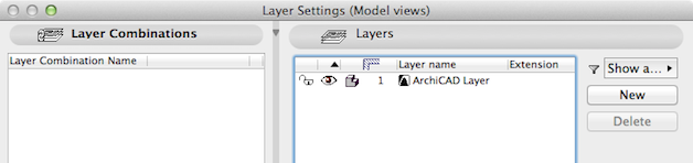
In ArchiCAD layers are good for no more than three things: visibility control, editing convenience, and improved rendering speed. Remember Revit gets by with none at all. There are better ways to categorize data. Among ArchiCAD data fields the Element ID offers the broadest functionality to identify and group elements for Interactive Schedules, Lists, Find and Select Criteria Sets, and the IFC Manager.

archicadobjectdefaultsettings628x353.png

You can assign an Element ID to any Construction Tool, Object, Zone, Fill, or Grid Element using up to 15 characters. You can edit it in the Tags and Categories panel, an Interactive Schedule, or the Element ID Manager. You can even display it in plan with element Label Settings.

Interactive Schedules

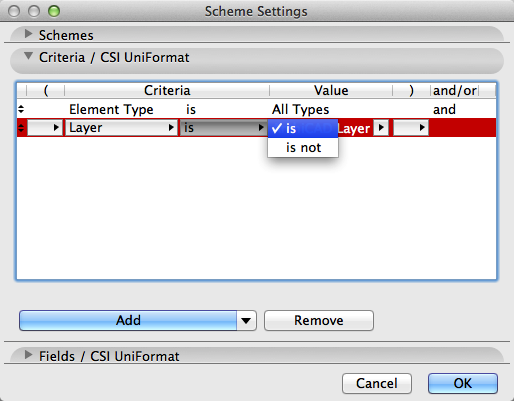
Scheme Settings are used to establish selection criteria for Interactive Schedules. The Element ID field offers nine conditional functions: greater than, less than, greater than or equal to, less than or equal to, starts with, ends with, contains, is, and is not. Other non-numeric fields, including Layer, offer two: is or is not. Of course you’re free to incorporate layers into the Scheme Settings, but the Element ID obviously packs more punch. From here it’s just a matter of nomenclature.

archicadschemesettingslayeris514x401.png

archicadschemesettingselementidstartswith514x401.png

Find and Select Criteria Sets

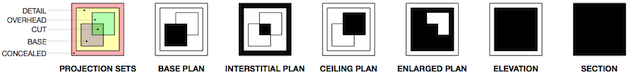
Consider a twist on a familiar tool. Using Find and Select you can create Criteria Sets to choose elements to display in the 3D Window and hence in a 3D Document. The filtering logic is similar to Interactive Schedules. So regardless of your layer strategy, you can isolate a particular system or set of components in a 3D Document. You can even use 3D Documents to create pseudo-plan views, elevations, and sections.

archicadfindandselectlayer402x264.png

archicadfindandselectelementidstartswith402x262.png

Unfortunately, 3D Documents must be updated manually. The process is somewhat involved, but once upon a time so were Schedules and Interior Elevations. So to incorporate new elements into a previously defined 3D Document—

  • Open the 3D Document.
  • Select Open 3D Source.
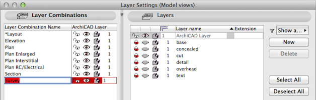
  • Make sure all the needed layers are visible. (Remember “The Power of One”)
  • Open Find and Select.
  • Apply the appropriate Criteria Set.
  • Select Show Selection/Marquee in the 3D Window.
  • Select Redefine the 3D Document. (Make sure it’s correct.)
  • Done

*Or if you’re not worried about preserving annotations from an earlier version, just go straight to the 3D Window and apply the Criteria Set to make a new 3D Document.

Nomenclature

Whether simple or complex, you should be systematic about setting Element ID’s. You’ll find the conditional functions starts with, contains, and ends with to be especially helpful. In simple situations, identify elements with prefixes like “W” for window and a numeral to indicate a unique instance or shared type, such as “W-07”. In sophisticated situations, adopt a standard like UniFormat. A fixed exterior window might be denoted as “B2020.20-07”, where “07” again refers to a particular instance or type. In a hierarchical system like UniFormat, the criterion “Element ID starts with B20” would select that window and all other exterior vertical enclosure elements.

IFC Attributes

If you’re into exchanging files, the IFC Element Name is the ArchiCAD Element ID, and it’s set by the ArchiCAD user. IFC also uses two unique identifiers set by the system: the GlobalId (the Globally Unique Identifier in the IFC model) and the Tag (the ArchiCAD GUID, which differs from the IFC GlobalId).

archicadifcmanagerarchicaddid628x176.png

The Take Away

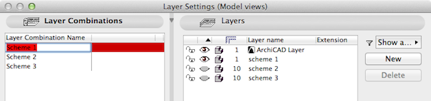
Manage drawings with layers and data with Element ID’s, so changes to one shouldn’t screw up the other. Use no more layers than the drawings require. Geometry first. Data later.

Connections: Follow additional commentary at LinkedIn/ArchiCAD.

The Power of One

maoposter740x185

How Many Layers Do You Really Need?

Last month in the LinkedIn ArchiCAD Group, Timothy Ball started a discussion entitled “Generating Correctly Named Layers – UK,” which got me thinking again about layers. He advocated naming layers according to Uniclass, a UK industry standard comparable to CSI’s UniFormat in the US. In my quest for interoperability, I once used UniFormat as the basis of my own layering system. However, it proved to be impractical given the large number of layers used and to be incomplete given the small number of categories accommodated. Even with 287 layers, it accommodated only 23 categories of building elements—after factoring in related layers to coordinate element display with renovation status, separate projections, and annotations. A pitiful outcome compared to 612 similar categories in UniFormat 2010. Then Graphisoft introduced the renovation filter, which helped a bit. But after reading John Maeda’s Laws of Simplicity, the realization hit me: the best use for layers in ArchiCAD was to provide a filter of last resort for controlling elements in 2D projections of the model (i.e., plans, elevations, and sections). That insight reduced my template to 21 layers.

“So, what can you do with just one layer—the mandatory, always-on, ArchiCAD Layer?”

Start Simple

Using only the ArchiCAD Layer, layer combinations are useless for controlling elements in 2D projections. But ArchiCAD 16 provides other tools for this purpose, such as story settings, individual element settings (including sections and elevations), and ArchiCAD’s other built-in document filters (model view options, renovation filter options, partial structure display, pen sets, and floor plan cut planes). The available model output is enough for schematic design in general and even construction documents on a simple project (although you might need a couple 2D worksheets for the electrical plans):

  • Site Plan
  • Floor Plans
  • Roof Plan
  • Interstitial Plans (with a few caveats)
  • Elevations
  • Sections
  • Interior Elevations
  • 3D Documents
  • Schedules and Lists

archicadlayersettings1layer628x148.png

When annotation requirements are minimal, interstitial plans showing concealed structural and/or mechanical elements can be modeled using the model view options to render the floor slabs transparent and the partial structure display to hide non-load bearing elements. Alternatively, 3D documents can be used to create similar drawings from the model, regardless of annotation requirements. Otherwise, draw other plans and details independently of the model using the 2D worksheet and detail tools. Here are some tips and limitations:

  • Place site elements on a separate story.
  • Display overhead objects as dashed elements on the floor plan.
  • Model elements and annotations share the same layer.
  • 3D elements shown in elevation and/or section also appear in plan (subject to partial structure display settings).
  • 2D elements may be added in one view without appearing in others.
  • Only modeled elements can appear in schedules or lists, which excludes 2D objects inserted into elevations, sections worksheets, or details.
  • Visual conflicts will likely arise in trying to model electrical fixtures in plan without additional layers, which will prevent creating an electrical fixture schedule from the model.
  • To control where objects such as trees and furniture appear pay special attention within object settings to the 3D detail level and floor plan display.
  • Objects appearing in the 3D window and hence 3D documents may be selected individually and/or by using the Find & Select tool. Rules for selection criteria can be created, edited, and named for future use, but updates must be performed manually.

Multiply Your Power:  Alternates

To explore alternate schemes, add one layer and one layer combination for each alternate and restrict the ArchiCAD Layer to shared elements.

archicadlayersettings3layerscolor628x148.png