

Wonders of a Virtual World
“So, what can you do with just seven layers?” Almost everything anyone ought to be doing with layers, no matter how many. Yes, I told you in the “Power of One” that my standard template has twenty-one layers, but for now seven is enough to introduce the principles of my system. Take note: visibility is king. For all that functional tracking stuff see my earlier post “Stop Worrying and Learn to Love the Element ID.”
Layer Concept
Begin with the ArchiCAD Layer and reserve it for layout elements. Reassign other elements, such as those from schematic design, elsewhere. The remaining layers are derived from standard orthographic projections. In plans the cutting plane segregates a building’s components into three natural categories: base elements, which fall wholly below the cutting plane; cut elements, which intersect it; and overhead elements, which lie wholly above it. Typical elevations include plan elements plus additional wall-mounted components, like baseboard or trim, that are too thin to show in a standard plan. These components, along with small elements one finds on an enlarged floor plan, constitute the detail for our fifth layer. Typical sections include both plan and elevation elements plus additional components concealed within floor or ceiling assemblies, which define our sixth layer. (See Euler Diagrams of combinations below.)
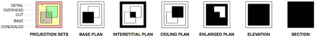
Regarding visibility, we can manage with just six layers by combining model elements with text and other annotations—until we include an enlarged plan. Why? The text and other annotations we need for it will be superimposed on those for the floor plan when we set up the layer combinations. So our seventh layer is reserved for text and other annotations needed for our base plans for the site, floors, and roof. We’ll find it’s our preferred location for any text or other annotations we wish to add to any drawing except other modeled plan views.
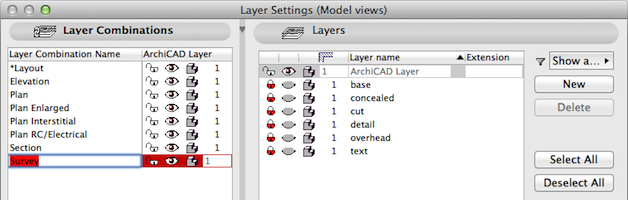
Layer Combinations and Layers
| *Layout | ArchiCAD Layer |
| Elevation | ArchiCAD Layer | base | cut | detail | overhead | text |
| Plan | ArchiCAD Layer | base | cut | text |
| Plan | ArchiCAD Layer | base | cut | text |
| Plan Enlarged | ArchiCAD Layer | base | cut | detail |
| Plan Interstitial | ArchiCAD Layer | concealed | cut |
| Plan RC/Electrical | ArchiCAD Layer | cut | overhead |
| Section | ArchiCAD Layer | base | concealed | cut | detail | overhead | text |
| Survey | ArchiCAD Layer | [xref] |
Modeled Drawings and Layer Combinations
| Site Plan | Plan |
| Floor Plan | Plan |
| Roof Plan | Plan |
| Reflected Ceiling/Electrical Plan | Plan RC/Electrical |
| Interstitial Plan | Plan Interstitial |
| Enlarged/Finish Floor Plan | Plan Enlarged |
| Elevation | Elevation |
| Section | Section |
| Interior Elevation | Elevation |
| 3D Document | [depends on view] |
| Survey | Survey |
Tips and Limitations
- Place site elements on a separate story, generally the lowest.
- Place electrical objects, text, and annotations on the overhead layer, regardless of their relation to the cutting plane. By default these will be visible on the reflected ceiling plan.
- Elements placed outside the 3D model, like those on 2D Worksheets or Details, cannot be used with Interactive Schedules, Lists, Photo Rendering, or Energy Evaluations.
- Use the interstitial plan to show concealed structural and/or service components.
- Use Object Settings for 3D Detail Level and Floor Plan Display to prevent modeled plants or furniture from appearing in 3D windows, elevations, or sections. Consider adding vegetation to elevations and sections as 2D annotations.
- Consider attaching a survey as an xref file, which will add xref layers. Edit layer combinations as needed to show survey data in plan. (It’s just xref layers. Who’s counting?)
- Provide unannotated presentation drawings by hiding the text layer.
- Provide other plan views using the 2D Worksheet tool.
- Provide construction details using the 2D Detail tool. A practical limit for displaying modeled elements is around 1:16 (3/4″=1’–0″).
Screenshots

Layout

Elevation

Plan

Plan Enlarged

Plan Interstitial

Plan Reflected Ceiling/Electrical

Section
Survey
