
How Many Layers Do You Really Need?
Last month in the LinkedIn ArchiCAD Group, Timothy Ball started a discussion entitled “Generating Correctly Named Layers – UK,” which got me thinking again about layers. He advocated naming layers according to Uniclass, a UK industry standard comparable to CSI’s UniFormat in the US. In my quest for interoperability, I once used UniFormat as the basis of my own layering system. However, it proved to be impractical given the large number of layers used and to be incomplete given the small number of categories accommodated. Even with 287 layers, it accommodated only 23 categories of building elements—after factoring in related layers to coordinate element display with renovation status, separate projections, and annotations. A pitiful outcome compared to 612 similar categories in UniFormat 2010. Then Graphisoft introduced the renovation filter, which helped a bit. But after reading John Maeda’s Laws of Simplicity, the realization hit me: the best use for layers in ArchiCAD was to provide a filter of last resort for controlling elements in 2D projections of the model (i.e., plans, elevations, and sections). That insight reduced my template to 21 layers.
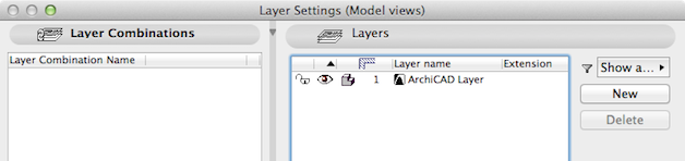
“So, what can you do with just one layer—the mandatory, always-on, ArchiCAD Layer?”
Start Simple
Using only the ArchiCAD Layer, layer combinations are useless for controlling elements in 2D projections. But ArchiCAD 16 provides other tools for this purpose, such as story settings, individual element settings (including sections and elevations), and ArchiCAD’s other built-in document filters (model view options, renovation filter options, partial structure display, pen sets, and floor plan cut planes). The available model output is enough for schematic design in general and even construction documents on a simple project (although you might need a couple 2D worksheets for the electrical plans):
- Site Plan
- Floor Plans
- Roof Plan
- Interstitial Plans (with a few caveats)
- Elevations
- Sections
- Interior Elevations
- 3D Documents
- Schedules and Lists
When annotation requirements are minimal, interstitial plans showing concealed structural and/or mechanical elements can be modeled using the model view options to render the floor slabs transparent and the partial structure display to hide non-load bearing elements. Alternatively, 3D documents can be used to create similar drawings from the model, regardless of annotation requirements. Otherwise, draw other plans and details independently of the model using the 2D worksheet and detail tools. Here are some tips and limitations:
- Place site elements on a separate story.
- Display overhead objects as dashed elements on the floor plan.
- Model elements and annotations share the same layer.
- 3D elements shown in elevation and/or section also appear in plan (subject to partial structure display settings).
- 2D elements may be added in one view without appearing in others.
- Only modeled elements can appear in schedules or lists, which excludes 2D objects inserted into elevations, sections worksheets, or details.
- Visual conflicts will likely arise in trying to model electrical fixtures in plan without additional layers, which will prevent creating an electrical fixture schedule from the model.
- To control where objects such as trees and furniture appear pay special attention within object settings to the 3D detail level and floor plan display.
- Objects appearing in the 3D window and hence 3D documents may be selected individually and/or by using the Find & Select tool. Rules for selection criteria can be created, edited, and named for future use, but updates must be performed manually.
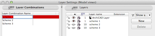
Multiply Your Power: Alternates
To explore alternate schemes, add one layer and one layer combination for each alternate and restrict the ArchiCAD Layer to shared elements.